Creatively Lazy or Just Smart Problem Solving by a DuLazy

What have you created to solve a problem with the least amount of effort to maintain it and operate it?
Problems to Solve – Example of the Week
Contributed by: Ken Dulaney
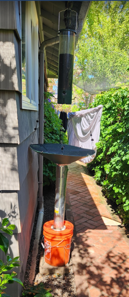
Problem: We love to feed the birds. We figured a squirrel proof feeder would do the job, but soon after the feeder was hung, the squirrels outwitted the first investment in squirrel proofing our feeder. The feeder displayed has a mechanism that permits the birds to sit on the perches while they feed, but if a squirrel tries to use it, the perch collapses and they fall to the ground. The squirrels figure out how to jump on the feeder and with their sharp claws hang on to the gaps in the feeder. They would eat seeds from the feeding ports upside down!
Furthermore, the seeds that were uneaten fell to the ground and attracted rats. This upset our neighbors as you can imagine.
Solution: The solution shown in the picture to the left was developed over several iterations. A piece was installed and when the squirrels defeated it, another solution was developed and installed. Additions and changes were made until the solution described here seemed to achieve squirrel proofing nirvana.
From top to bottom, there is a squirrel baffle to keep them from dropping down on the feeder from the roof. These are readily available from Amazon. Next there is the feeder hanging from a hook attached to the bottom of the baffle. Attached to the same point are 4 coated rust proof cables from which the seed catcher hangs. The cables are adjustable in length.
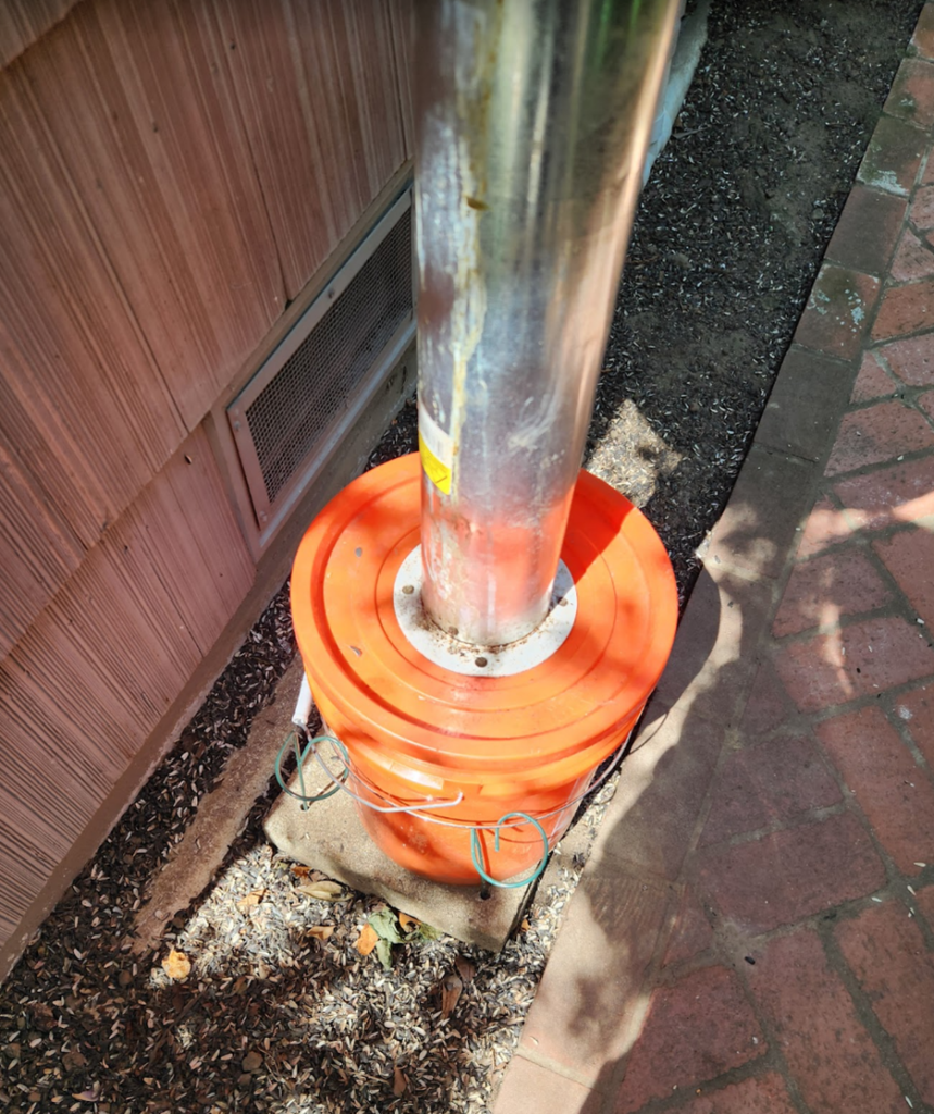
Discarded seeds drop into a 24-inch-wide squirrel baffle that is inverted to act as a funnel. The hole in the bottom permits the seeds to drop down a 4” metal heating duct about 3 feet in length into a 5-gallon Home Depot bucket with lid. The bucket has a 4-inch hole cut in the lid. This hole supports a standard fitting that permits the duct to be removed easily.
The bottom of the bucket was drilled with about 10 3/8-inch holes to permit any liquids to flow out of the bucket. The bucket is placed on a 12-inch paver stone which is required to prevent the rats from tunneling under the bucket. Four ½-inch holes were drilled into each corner of the stone using a masonry bit. These holes support 4 stakes which in turn support a metal ring that prevents the squirrels from tipping over the bucket. These rings (hoops) can be found again on Amazon.
The 4-inch duct, the bucket, the paver and the right stakes can be seen here. The collar for the duct can be seen in the lid of the bucket.
The top squirrel baffle, the hook for the feeder and the 4 cable attachments can be seen in this detail
The inverted baffle used as a funnel for discarded seeds can be seen below with the end of the cables that hold the baffle in place. Note that there are hooks to attach to holes in the baffle and a push button lock that permits adjustment of the cable length. One end of the cable is terminated with a ferrule to prevent over extension. Tie wraps are used to keep the cables together.

Coated chicken wire (1/4-inch openings) is used to prevent the squirrel from sitting in the baffle and eating the seeds. It is tied down with 4 turn button locks so the screen can be removed for cleaning.

Operationally, the birds feed and drop seeds. The funnel guides them to an opening to the 4-inch duct and down into the bucket. The bucket is emptied about once per week depending on the activity at the feeder.
The squirrel can still get to the feeder, but we believe that given little food is being dispensed that they will go elsewhere. But the big win has been the elimination of rats and not having to clean the mess every so often. A more ingenious feeder is on the way from Duncraft that should become the final solution.
Solving Door Ding Damage in the Family Garage
Problem: Many small garages can accommodate two cars, but the placement of the cars has to be just right a) to enable the driver at a minimum to exit the car on the right side without the car door hitting and potentially damaging the car on the left side and b) to prevent the cars from hitting anything placed on the back wall of the garage. This problem is most acute in older and urban areas and is especially acute in European garages.
Solution: We equipped the garage with several protection and alignment control features that have now solved the problem.
- Rubber bumper bolted to the floor – The following was ordered from amazon.com
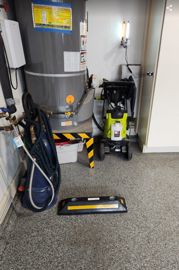
A car was placed in the desired position and the bumper snugged up to the back of one of the tires. The distance to the walls was measured. Car was backed out and using a masonry drill and concrete anchors, the bumper mounted to the garage floor.
- Garage frame distance marker – It is important to ensure that as the car is entering the garage that it is located at the proper distance from, in this case, the left wall. The chosen method to ensure this was to use the left outside mirror of the car aligned to a flexible sign mounted to the garage frame. The sign has to be flexible so as not to damage the car or break if the car is misaligned. To achieve this, a spring doorstop was purchased at Home Depot (these are mounted at the bottom of doors to ensure that the door handle doesn’t damage the wall when opened). A small wooden stick was inserted through the rubber end of the doorstop and clamped to it so that it would not rotate (gluing is not desired because the stick must be moved in/out when adjusting the position of the sign). A small stop sign is mounted to the end of the stick and glued in position. Mounting the assembled to the unit must ensure that the garage door will not hit the sign but it must be close enough to the garage door frame to ensure proper passage of the car. (see diagrams below)
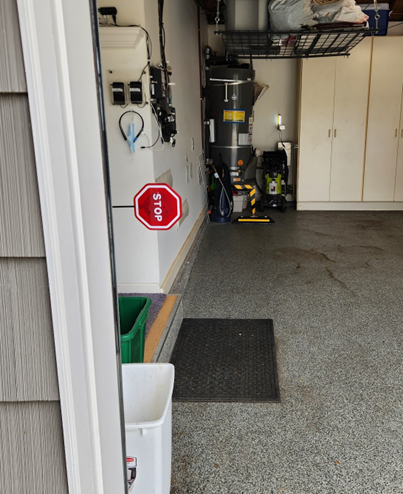
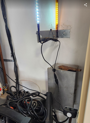
- Parallax view alignment lights – Once the car enters the garage, a motion sensor turns on two stick lights that are mounted on the back wall, one in front of the other separated by about 8 inches from front to back. A Simpson angle bracket purchased at Home Depot is used to hold them in place with plastic zip ties mounted through holes drilled in the angle bracket. The back light is fronted with a thin piece of yellow transparent plastic. When this light is visible it means the car is not in proper alignment.
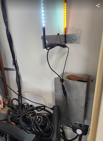
The following components came from amazon.com. A typical anchor is used to mount the L bracket to the wall.
USB-Powered Motion sensor https://www.amazon.com/dp/B09X19DMN1?ref=ppx_yo2ov_dt_b_product_details&th=1
Two LED stick lights https://www.amazon.com/dp/B0CP2FHN78?ref=ppx_yo2ov_dt_b_product_details&th=1
The motion detector is mounted so that it faces the front grill of the car. A USB power supply is connected to the motion detector and then in turn a USB splitter is connected to the two stick lights.
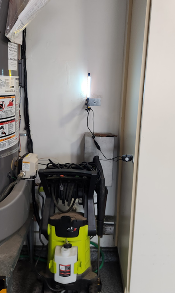
The effect of this device is that if you are properly aligned in the parking space, you will see only the front white light (second photo below). If you are not aligned, you will see two lights.
- Laser pointer – This is used to confirm that the car is in the right spot and to determine if it is not in the exact correct spot, how far left or right the car is located. It is entirely expected that each time the car is parked it may be slightly off left or right, but the driver must know how much that is so they can be assured that they are within the tolerances allowed for parking the vehicle.
This is the unit ordered from amazon.com.
It has two lasers for the two cars in the garage and shines a line not just a dot on the vehicle. The car being parked on the left side of the garage discussed here uses a line pointed from front to back and directed to a prominent area on the dash. Noting how far left or right the line is from the perfect position tells the driver whether he is withing the parking tolerances.
NOTE: For the car on the right, the laser line is directed side to side so that the car knows when it is placed properly front to back. This car’s placement is doubly check with a hanging ball. The left to right placement is assured by having the driver simply watch the right outside mirror as it passes the garage frame.
5) Garage car door wall protectors – Once the car is parked, opening the left doors in this case might cause them to impact the wall. These protectors will prevent damage.
Example from amazon.com
Solving Indoor Plants Even Sunlight – The rotating plant & base solution
Designer and Contributor: Ken Dulaney
Large Potted Plant Rotator
Problem: We have a beautiful New Zealand laurel in our living room. It’s in the corner near a 4 pane Anderson sliding door which gets good sunlight. The problem is that it only gets sunlight on one side while the back withers. Clearly it would make sense to rotate it, but I am too lazy to do this continually.
This is a photo of the plant int its container prior to installing the plant rotator.

Solution: I decided that I needed an automated system to rotate the plan periodically during the day.
The concept basically was to use a Lazy Susan bearing which would permit the plant to rotate and to power the rotation via a BBQ rotisserie motor that would come on for a few seconds every half hour.
The BBQ rotisserie motor was easy to find on Amazon. When it arrived, it was noted that the rotating shaft was square, typical of most BBQ applications. That meant that to ensure the motor would rotate the plant which could be heavy the hole in the platform on which the potted plant sat would have to be square and a tight fit. Slippage was not an option.
It was decided to mount 12-inch x 12-inch tiles on top of the bearing to hold the plant and to permit water runoff into the basin in which the potted plant is held. However mounting things to the underside of a ceramic tile is a bit difficult. So, I created a sandwich of a rubber floor tile and a ceramic tile. This permitted the motor to be strapped to the underside of the rubber tile. The Lazy Susan bearing was placed on top of the ceramic tile and then another rubber / ceramic tile sandwich placed on top of the bearing. So, we have a stack consisting of motor, rubber tile, ceramic tile, Lazy Susan bearing, rubber tile and ceramic tile. See below.
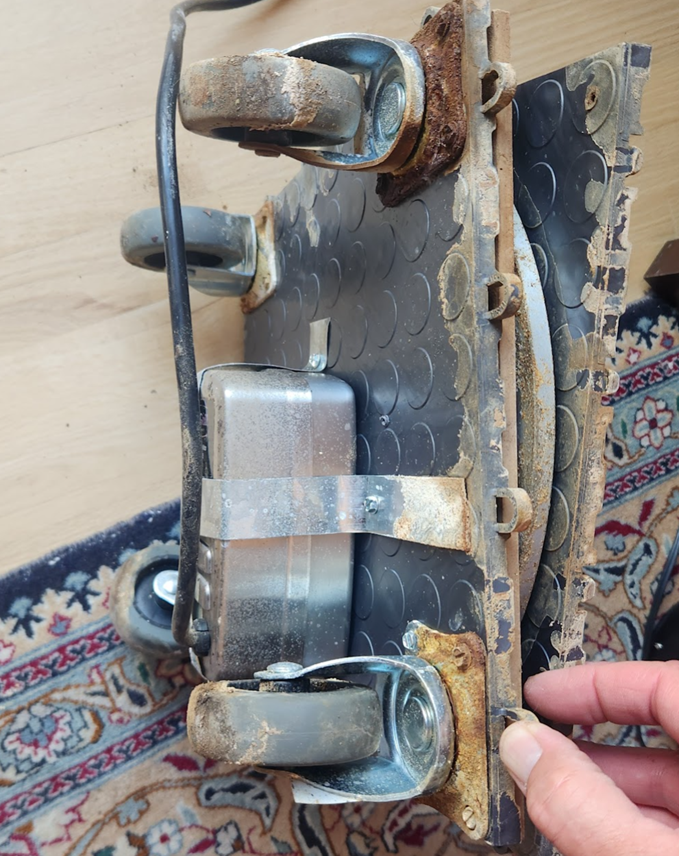
The motor is strapped to the bottom of the rubber tile as shown in the picture above. A generous hole was drilled through the bottom rubber / ceramic tile layer sufficiently large so that the BBQ motor shaft can rotate. The shaft is threated through the center of the Lazy Susan bearing and into the rubber tile on top of the bearing only. The hold in the rubber tile must be square and exactly the dimensions of the BBQ motor shaft. See photo below. This will ensure that the full power of the motor is transferred to the tile. The shaft should not penetrate the ceramic tile. It is important that this tile remains intact so that water that may drip from the plant does not run down towards the BBQ motor.
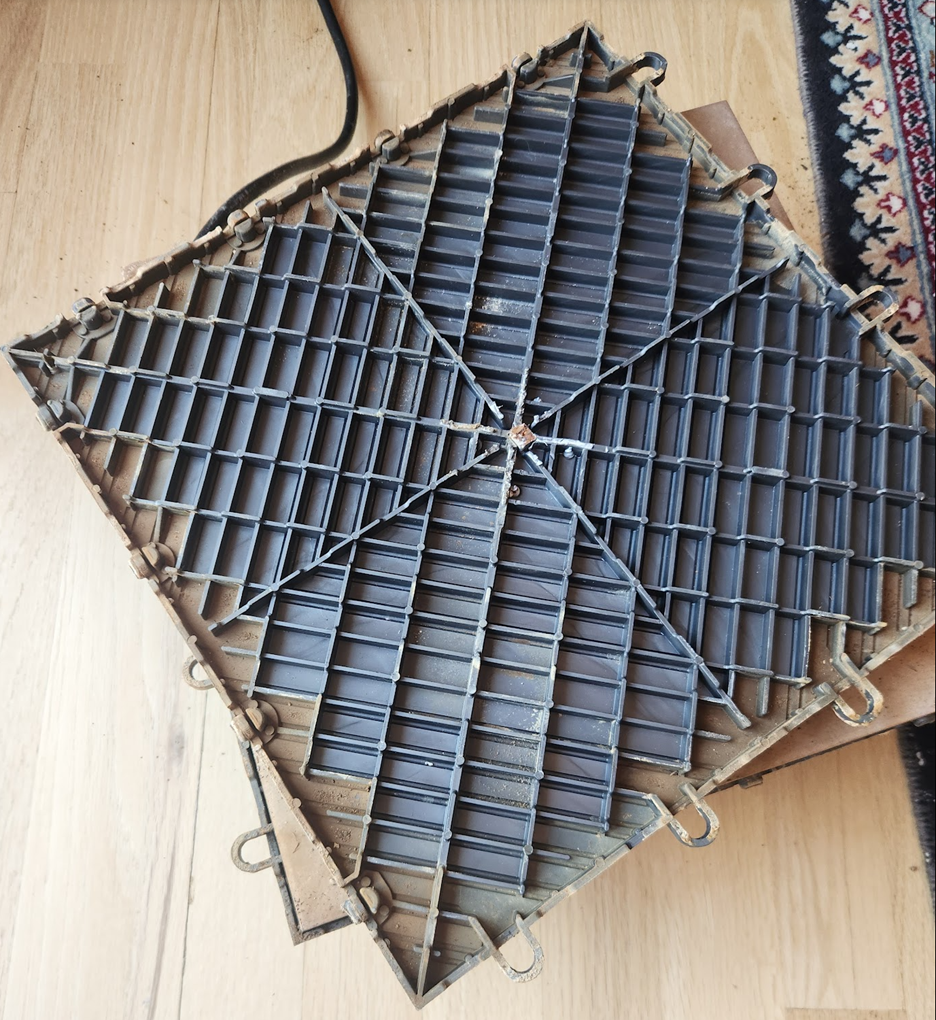
In the above photo you will see 4 wheels attached to the underside of the floor tile stack. The reason for this is that as the stack turns, it may push against the sides of the container that holds the plant (not the pot in which the plant is grown). The wheels permit some movement.
The power cord for the BBQ motor must be routed away from the stack so that it doesn’t become entangled.
The fully assembled unit outside its container is shown below.
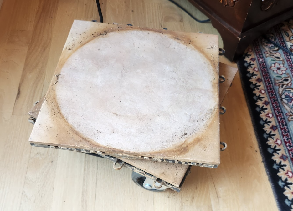
The power cord is attached to a Gosund WiFi plug. The plug is programmed to turn on for 2 seconds every half hour from 8AM until 8PM. Unfortunately, Gosund does not have a recursive programming model, so you have to program each on, 2 second delay and off sequence manually. It is important also to program a number of” device off” commands, a delay and more device off commands for each half hour sequence in case the cloud cannot be reached. If the off command fails, the plant will rotate until the next sequence occurs.
This system also serves as an odd type of clock, rotating every ½ hour. I often appreciate knowing the time if I happened to pass by when the plant turns.
After a year, our plant is growing on all sides and the unit seems to be highly reliable.
